






Tuesday, May 25, 2021

Monday, May 24, 2021
Civil Engineering Books Collections


Saturday, May 22, 2021
Maximum Spacing Between columns
SIZE OF
COLUMN BEAM
Column
NBC 105:2077
Requirements of this section shall apply to columns resisting earthquake-induced effects, in which the factored axial compressive stress due to gravity and earthquake effects exceeds 0.08fck.
- The minimum dimension of a column shall not be less than 20 db, where db is diameter of the largest diameter of longitudinal reinforcement bar in the beam passing through or anchoring into the column at the joint.
- The minimum dimension of column shall be 300 mm.
- Columns shall preferably have width-to-depth ratio of more than 0.45.

Fig:
Requirement for minimum size of column member
IS
13920:1993
These requirements apply to frame members which have a factored axial stress in excess of 0.1 fck under the effect of earthquake forces.
- The minimum dimension of the member shall not be less than 200 mm. However, in frames which have beams with centre to centre span exceeding 5 m or columns of unsupported length exceeding 4 m, the shortest dimension of the column shall not be less than 300 mm.
- The ratio of the shortest cross sectional dimension to the perpendicular dimension shall preferably not be less than 0.4.
Beams
NBC 105:2077
Requirements of this section shall apply to beams resisting earthquake-induced
effects, in which the factored axial compressive stress does not exceed 0.08fck. Beams,
- Beams shall not have width less than 200 mm
- Beams shall not have depth D more than 1/4th of clear span.
- Width of beam bw shall not exceed the width of supporting member
IS
13920:1993
These requirements apply to frame members resisting earthquake induced forces and designed to resist flexure. These members shall satisfy the following requirements.
- The factored axial stress on the member under earthquake loading shall not exceed 0.1 fck.
- The member shall preferably have a width-to-depth ratio of more than 0.3.
- The width of the member shall not be less than 200 mm.
- The depth D of the member shall preferably be not more than l/4 of the clear span.
MAXIMUM DISTANCE BETWEEN TWO COLUMN IN THE BUILDING
Column: A column or pillar in architecture and structural engineering is a structural element that
transmits, through compression, the weight of the structure above to
other structural elements below. In other words, a column is a compression
member.
There are no any particular rule for determining the
spacing between the two columns. It all depends upon the type of structure and
Architecture and Structural Engineer’s considerations. Architecture are always
consider larger spacing in building to be used for different purpose while
structure engineer are to be always try
to make the structure safe economy and ensure the integrity of the structure
and prefer the grid system of column.

There are 2 major factor for determining the spacing of
column
- Type
of structure
In general residential building there
are no heavy load in the structure so the distance between column may be
increases considering structural safety while increasing the distance between
two column the size of column and depth of beam also increased it may lead the
increase the cost of structure.
Generally 3-4m in ordinary building
and in large building it may be up to 6-9m column spacing are used. Maximum 5m
to 7.5 m and minimum 2.5m kept the distance between the two columns.
- .
Architecture
and structure engineer consideration
Architecture are always consider
larger spacing in building to be used for different purpose while structure
engineer are to be always try to make
the structure safe economy and ensure the integrity of the structure and prefer
the grid system of column
Sunday, February 28, 2021

Wednesday, January 27, 2021
Bar Bending Schedule(BBS)
INTRODUCTION
Bar Bending Schedule is a summary of the reinforcement in a tabular formm which includes the following information. Bar bending schedules are very important out of detailing and should give the following information:Identification of the structural
member(s),
- Position of the bars in the
structure,
- The bar mark,
- The diameter or size of bar,
- The number of bars of one type in
each structural member,
- The total number of bars of each
type,
- The total straight length of the
bar,
- The shape and bending dimensions
of the bar,
- The details of bar chairs can also
be included,
- Remarks, if any.
The Various Standard Size of round steel Bars along with Their weight are Shown in Table.
Diameter of Bars
Weight of Bar(kg/m)
6
0.22
8
0.39
10
0.62
12
0.89
14
1.2
16
1.58
18
2
20
2.47
22
2.98
25
3.85
28
4.84
32
6.32
36
8
40
9.87
Measurementof Bending Dimensions of Bars For R.C.C.


SAMPLE OF BBS
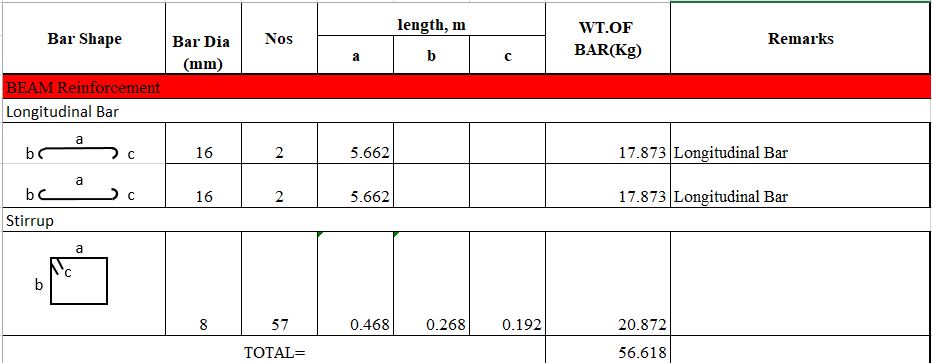
Numerical Examples :
BEAM

CALCULATION Longitudinal bar:L= total length-clear cover+hook =6000-2*25+9*16*2 =5662mmStirrup: =2a+2b+Hook a=depth-clear cover -Dia of bar b=width-clear cover -Dia of bar a=300-2*25-2*8 =234mm
Identification of the structural member(s),
- Position of the bars in the structure,
- The bar mark,
- The diameter or size of bar,
- The number of bars of one type in each structural member,
- The total number of bars of each type,
- The total straight length of the bar,
- The shape and bending dimensions of the bar,
- The details of bar chairs can also be included,
- Remarks, if any.
|
Diameter of Bars |
Weight of Bar(kg/m) |
|
6 |
0.22 |
|
8 |
0.39 |
|
10 |
0.62 |
|
12 |
0.89 |
|
14 |
1.2 |
|
16 |
1.58 |
|
18 |
2 |
|
20 |
2.47 |
|
22 |
2.98 |
|
25 |
3.85 |
|
28 |
4.84 |
|
32 |
6.32 |
|
36 |
8 |
|
40 |
9.87 |


b=200-2*25-2*8 =134mmhook= 2*12*8 =192mmNo of Stirrup= (distance/spacing )+1 =(5600/100)+1 =57 No
Reference:- is.sp.34.1987 Handbook on Concrete Reinforcement and Detailing

- is.sp.34.1987 Handbook on Concrete Reinforcement and Detailing
- is.2502.1963Code of Practice for Bending and Fixing of Bars for Concrete Reinforcement
- is.2502.1963Code of Practice for Bending and Fixing of Bars for Concrete Reinforcement
Tuesday, January 12, 2021

Monday, January 4, 2021
Wednesday, May 13, 2020
Estimating and Costing Chapter One Note
Item No.
|
Description
of work
|
Unit of
Measurement
|
Unit of
Payment
|
1.
|
Earthwork
|
||
1.1
|
E/W in excavation in
foundation
|
m3
|
Per % m3
|
1.2
|
E/W in filing
|
m3
|
Per % m3
|
1.3
|
Surface dressing
|
m2
|
Per m2
|
1.4
|
Surface excavation
|
m2
|
Per m2
|
2.
|
Brickwork
|
||
2.1
|
Brick on flat soling
|
m2
|
Per m2
|
2.2
|
B/W in foundation
|
m3
|
Per m3
|
2.3
|
B/W in superstructure
|
m3
|
Per m3
|
2.4
|
B/W in arches
|
m3
|
Per m3
|
2.5
|
B/W in Cornice
|
m
|
Per m
|
2.6
|
Half brick thick wall
|
m2
|
Per m2
|
3.
|
Concrete works
|
||
3.1
|
PCC in foundation
|
m3
|
Per m3
|
3.2
|
Lime concrete in foundation
|
m3
|
Per m3
|
3.3
|
PP for RCC walls
|
m3
|
Per m3
|
3.4
|
50mm thick PCC in floor
|
m2
|
Per m2
|
3.5
|
Formwork for RCC work
|
m2
|
Per m2
|
3.6
|
Steel Reinforcement
|
Kg or MT
|
Per kg or MT
|
4.
|
Wood work
|
||
4.1
|
Wood works for doors and
window frame
|
m3
|
Per m3
|
4.2
|
Doors and window shutters
|
m2
|
Per m2
|
4.3
|
Wood works for trusses
|
m3
|
Per m3
|
4.4
|
Wood works for rafters, wall
plate etc.
|
m3
|
Per m3
|
4.5
|
Wood work for false ceiling
|
m2
|
Per m2
|
4.6
|
Wooden partition
|
m2
|
Per m2
|
5.
|
Iron works
|
||
5.1
|
M.S grill
|
m2
|
Per m2
|
5.2
|
Tubular trusses and purlins
|
Quintal or kg
|
Per kg
|
6
|
Flooring works
|
||
6.1
|
Sand filling
|
m3
|
Per m3
|
6.2
|
Cement sand screed
|
m2
|
Per m2
|
6.3
|
Marble flooring
|
m2
|
Per m2
|
6.4
|
Flagstone flooring
|
m2
|
Per m2
|
7.
|
Roofing Work
|
||
7.1
|
C.G.I sheet roofing
|
m2
|
Per m2
|
7.2
|
Tile roofing
|
m2
|
Per m2
|
7.3
|
C.G.I sheet on gutter ridge
|
m
|
Per m
|
7.4
|
Tile on ridge
|
m
|
Per m
|
8.
|
Plaster and Pointing works
|
||
8.1
|
Pointing works
|
m2
|
Per m2
|
8.2
|
Plastering works
|
m2
|
Per m2
|
9.
|
Painting and Polishing works
|
||
9.1
|
Enamel Painting
|
m2
|
Per m2
|
9.2
|
Washable distemper
|
m2
|
Per m2
|
9.3
|
French Polishing
|
m2
|
Per m2
|


